Mud Motors – How Downhole Motors Turn and Steer the Bit
Picture a drill string thousands of feet long, and now imagine the bit at the bottom spinning faster than the pipe above it. Sometimes the pipe isn't turning at all, yet the bit keeps cutting. That trick comes from a mud motor, one of the most useful tools in a directional driller's kit. So what is actually happening down there, and how does a mud motor turn and steer the bit?
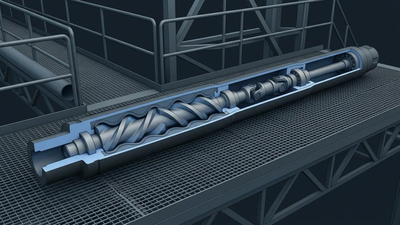
A mud motor is a downhole motor that uses the flow of drilling fluid to spin the bit, so the bit can turn without the whole drill string rotating. Mud pumped down the pipe is forced through a power section made of a spiral steel rotor inside a rubber-lined stator. As the fluid pushes its way through, it makes the rotor turn, and that rotation passes through a transmission and bearing section to the bit. With a small bend built into the housing, the driller can point the bit and "slide" to change the well's path, or rotate the string to drill fairly straight.
What Is a Mud Motor, in Plain Terms?
A mud motor is a hydraulic motor that lives in the bottomhole assembly, right above the bit. Its power source is the drilling fluid (mud) that the rig's pumps are already circulating. You'll also hear it called a downhole motor or a positive displacement motor, usually shortened to PDM.
Here's an everyday picture. Think of squeezing toothpaste out of a tube. The paste moves because a sealed pocket of it gets pushed along. A mud motor works on the same idea, except the moving pockets of mud force a steel shaft to rotate as they travel.
The industry's formal definition is short and worth reading. The SLB Energy Glossary entry on the mud motor describes it as a positive-displacement drilling motor that uses hydraulic horsepower from the mud to drive the bit.
How Does a Positive Displacement Motor Work?
A positive displacement motor works because its rotor and stator are shaped so that mud can only get through by turning the rotor. This design is often called the Moineau principle, after the engineer who developed this type of progressing cavity pump. Run the pump backward, so to speak, and you get a motor.
This is how the power section works. The rotor is a helical steel shaft with a set number of lobes. The stator is a steel tube lined with molded elastomer (a tough rubber) that has one more lobe than the rotor. Because of that mismatch, sealed cavities form between them. Mud entering the top fills those cavities, and the pressure pushes the rotor around so the cavities progress down the motor.
Lobe Configuration: Speed Versus Torque
Motors are described by their lobe ratio, such as 1:2, 4:5 or 7:8. The first number is rotor lobes and the second is stator lobes. The trade-off is simple and very useful to remember:
| Lobe ratio | Bit speed | Torque | Typical fit |
|---|---|---|---|
| Low (e.g., 1:2) | Higher | Lower | Bits and jobs that favor higher RPM |
| Medium (e.g., 4:5) | Moderate | Moderate | General directional work |
| High (e.g., 7:8) | Lower | Higher | PDC bits that need lots of torque |
Bit speed also rises with flow rate. More gallons per minute through the power section means the rotor turns faster. Torque, on the other hand, tracks the pressure drop across the motor, which climbs as you put more weight on the bit.
What Are the Main Parts of a Mud Motor?
From top to bottom, a typical mud motor has five sections. Each one has a single job, which makes the tool easier to understand than it looks.

- Dump (bypass) valve: Lets mud fill or drain the drill string during trips so you aren't pulling a wet string or running in dry. It closes once circulation starts.
- Power section: The rotor and stator, where hydraulic energy becomes rotation.
- Transmission section: The rotor doesn't just spin, it also wobbles in an off-center path. A flexible shaft or universal-joint assembly turns that wobble into clean, concentric rotation.
- Bearing section: Thrust bearings carry the weight on bit and the hydraulic thrust, and radial bearings keep the shaft centered. Bearings can be mud-lubricated or sealed in oil.
- Drive shaft and bit box: The bit screws onto this rotating shaft at the very bottom.
The adjustable bend usually sits between the power section and the bearing section, which is why it's so close to the bit.
How Does a Bent Housing Steer the Well?
A bent housing is a small, fixed angle built into the motor body, often adjustable at surface across a range of roughly zero to three degrees. That bend tilts the bit slightly off the axis of the string. It doesn't sound like much, but over a few dozen feet it changes the hole direction in a big way.
Drillers use the bend in two modes:
- Sliding: The string is not rotated from surface. The driller orients the bend (the "toolface") in the desired direction, and only the motor turns the bit. The hole curves toward the toolface.
- Rotating: The whole string turns from surface while the motor keeps spinning the bit. The bend now points every direction in turn, so it averages out and the hole goes roughly straight ahead.
The driller needs to know where the bend is pointing, and that comes from the survey tools just above the motor. That's where measurement while drilling earns its keep, sending toolface and inclination readings to surface in real time.
What Are the Limits of a Downhole Motor?
Mud motors are workhorses, but they have limits we have to respect. Most of them trace back to the rubber in the stator.
- Temperature: Elastomers soften and break down at high temperature, so very hot wells need special stator compounds or a different tool.
- Mud chemistry: Some oil-based muds and additives make the rubber swell, which tightens the fit and can tear the lobes ("chunking").
- Stalling: Pile on too much weight and the rotor stops while mud pressure spikes. Repeated stalls damage the stator fast.
- Sliding friction: In long horizontal wells, the non-rotating string drags on the low side of the hole, making it hard to get weight to the bit.
Newer designs use even-wall stators, where a thin, uniform rubber layer sits over a shaped steel tube. That gives more power from the same length and handles heat better than a thick rubber liner.
Mud Motor vs. Rotary Steerable: Which Is Better?
Neither is better in every well. A rotary steerable system steers while the whole string keeps rotating, so the hole tends to be smoother and cleaner, and there's no sliding friction. That matters a lot in long laterals.
A mud motor costs less to run, is simpler to service, and is very forgiving in many wells. It's also common to run a motor above a rotary steerable, adding bit speed and torque while the steering tool does the pointing. The right choice depends on the well plan, the budget and how hard the rock is.
How Does a Mud Motor Turn and Steer the Bit?
The whole tool comes down to one neat idea: mud has to push a spiral rotor around to get through the stator, and that turning drives the bit. Lobe count sets the balance between speed and torque, and the bearing section carries the load.
Steering comes from the bend. Slide with the bend pointed where you want to go, then rotate when you want to hold a straight line. If you're learning directional drilling, get comfortable with that slide-and-rotate rhythm first. Almost everything else builds on it.